Ps.if you want it all standard keep the cams standard too
1 Like
A collection of companies doing special things for VF engines would be nice.
I have two spare cam sets with pitting for RF/G. From Murphy’s point of view it would be better to have at least one set repaired so the fitted will last longer.
In Germany we have Campro . For me it is just arround the corner, but they had “problems” with R camshaft in the past. They use high temperature in the hardening process which can cause the springs of the gear train braking into pieces.
I took my worst cam and disassembled the rivets. You demount the springs, but you need rivets and someone to handle them.
Why the hell Honda used 46 tooth sprocket and not 44/48. If it would be a divider by four you can turn them by 90° and switch front/rear.
I took the cams and followers to Phil today & he thinks 3-4 weeks…
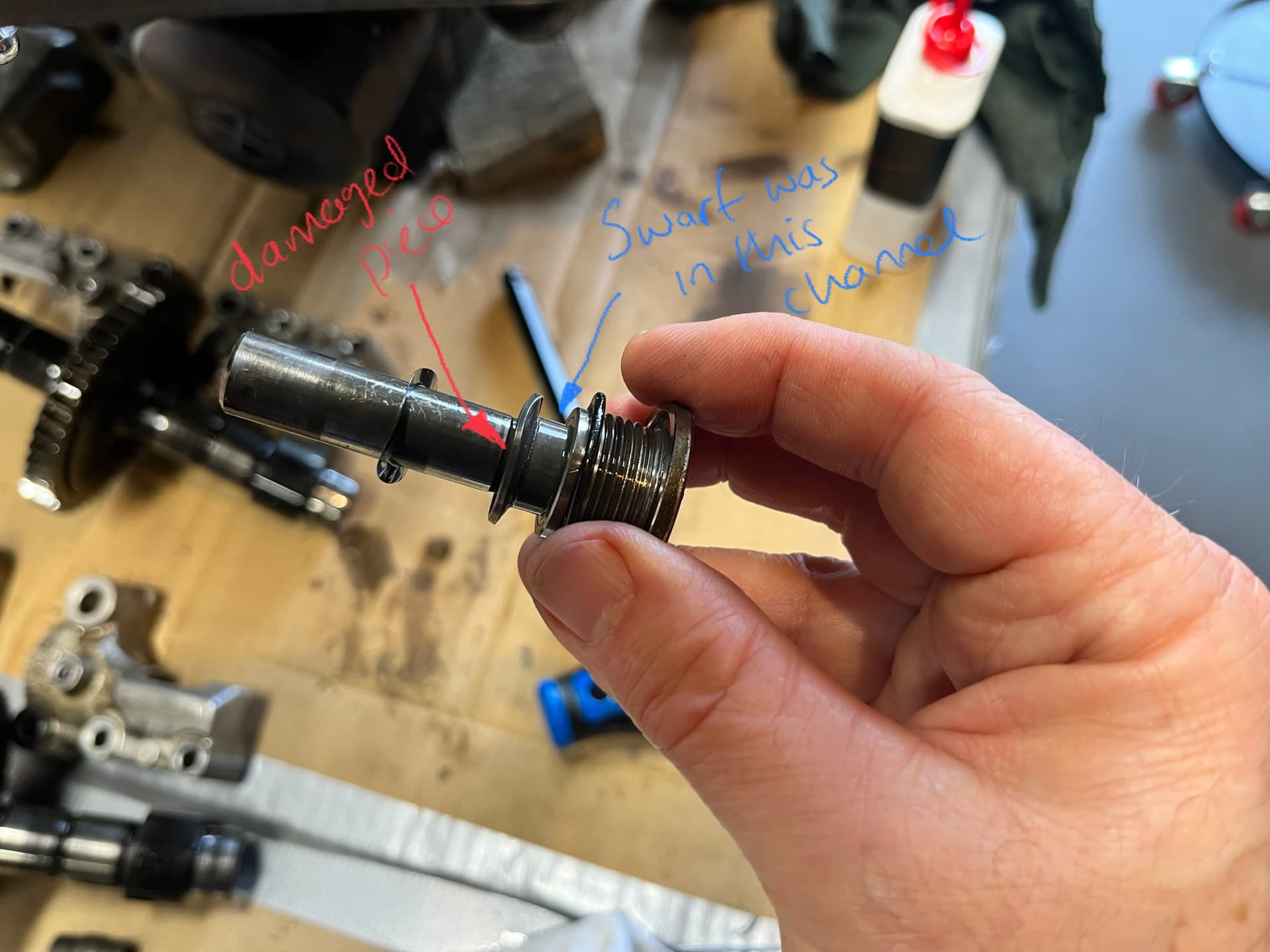
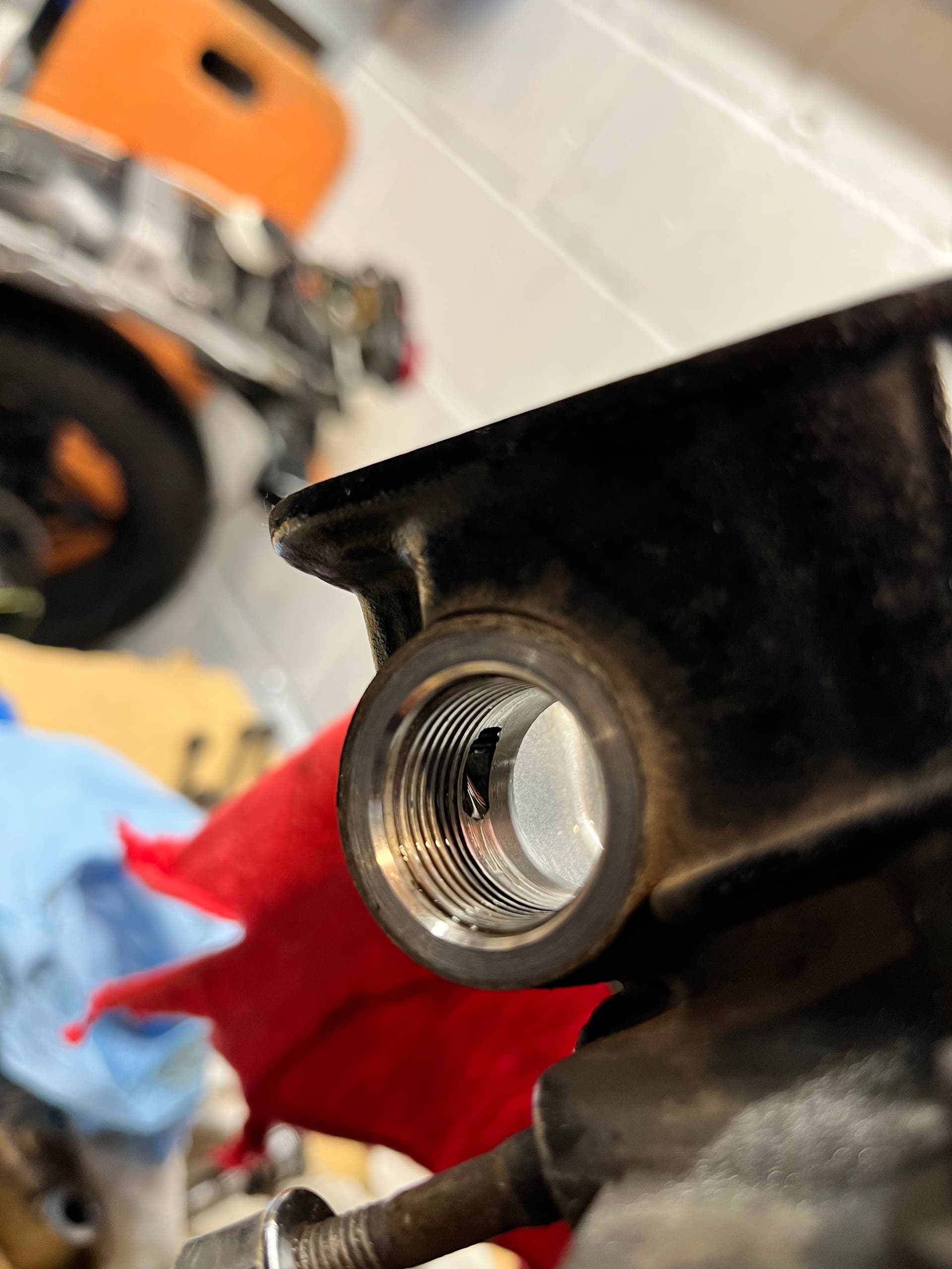
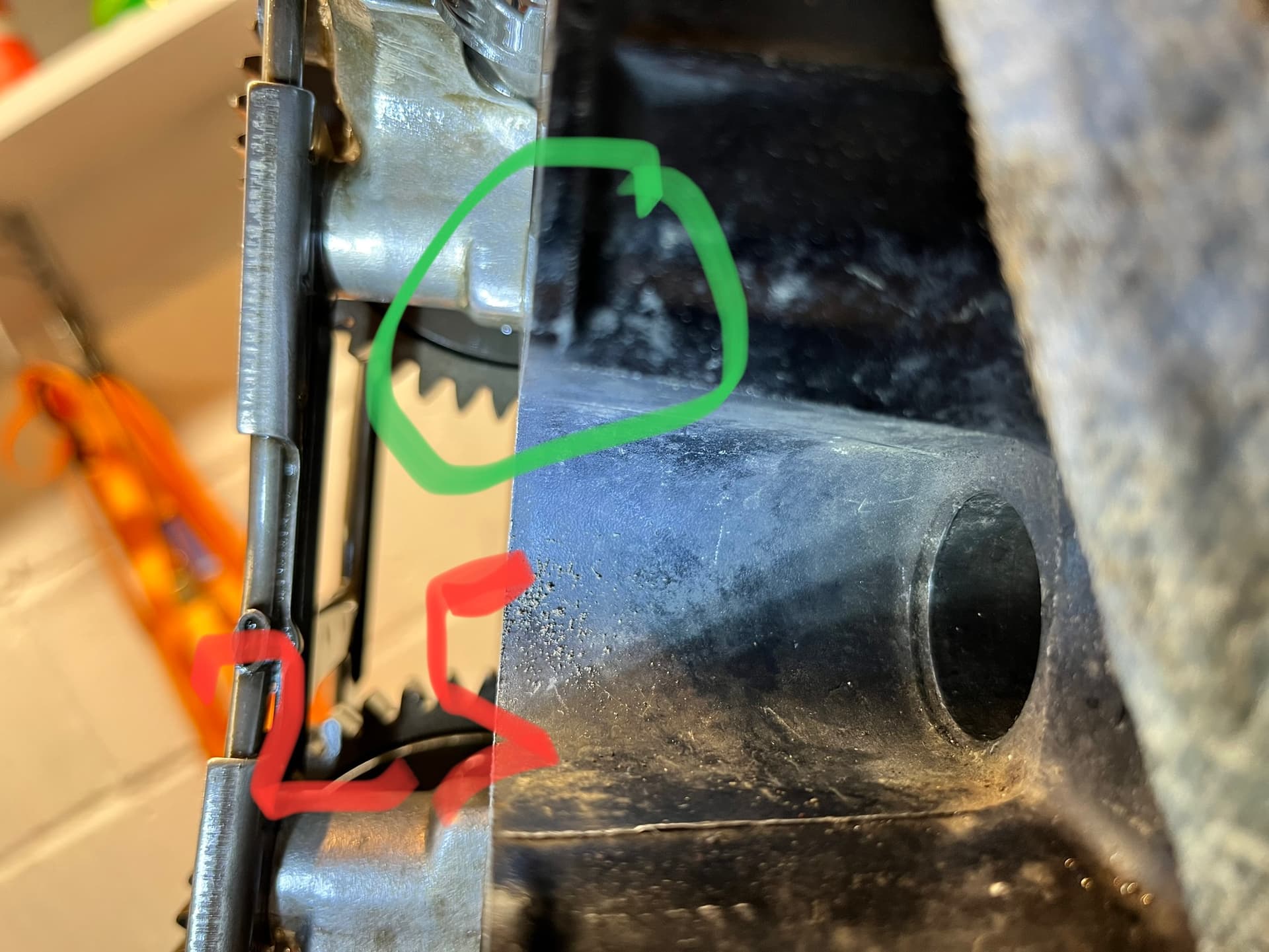
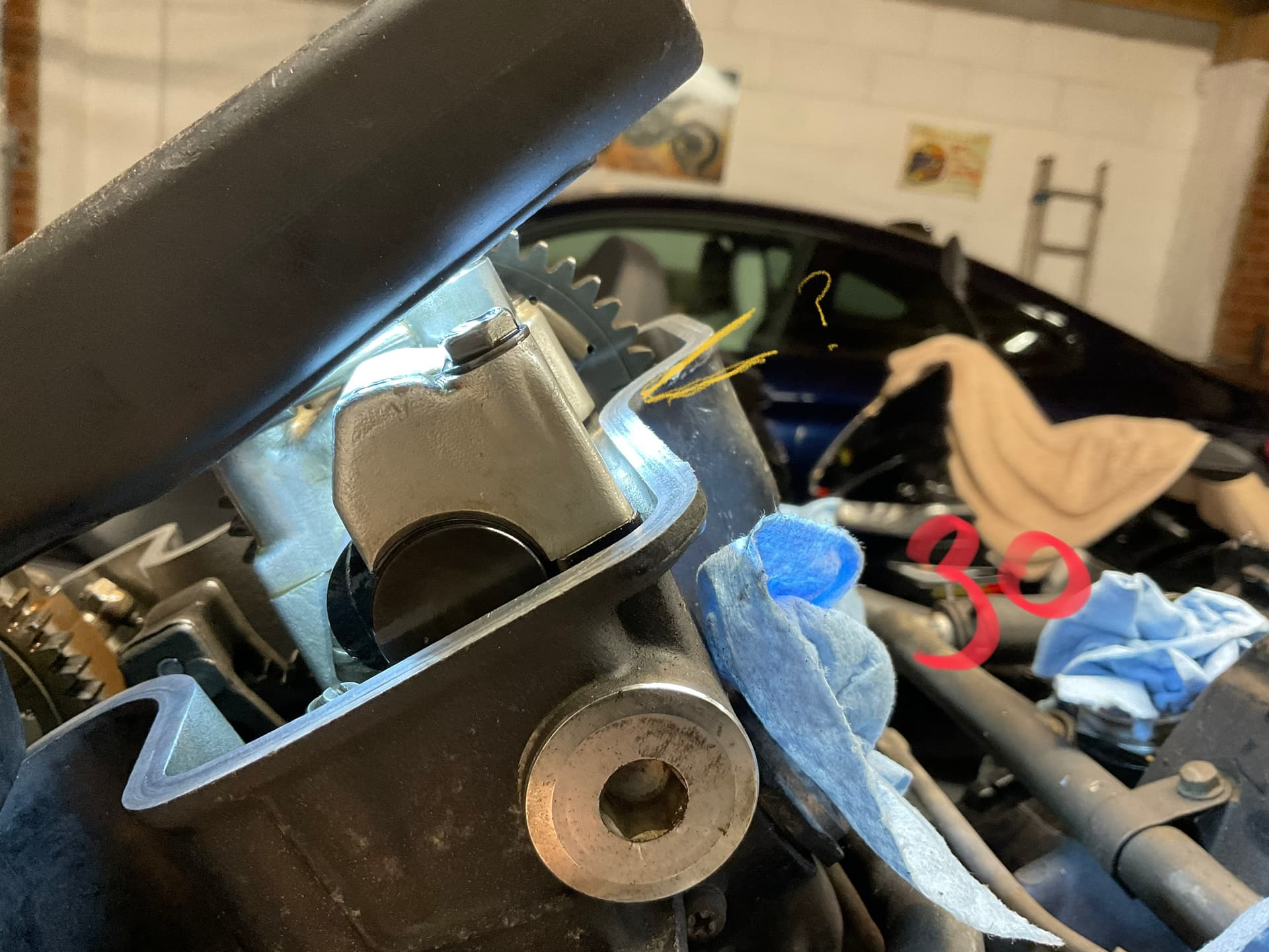
I did notice on removing the followers that 2 of the rocker shafts had damage see photo. This lip (red arrow on 1st photo) had snapped at one point to allow this bend profile, there was also quite a bit of swarf collected in the channel which I wiped out before I took the photo but show where it was with a blue arrow. Not sure where the swarf is from, maybe cam, follower material of from the hole this rocker sits in but the hole doesn’t look too damaged…see 2nd photo
Any ideas what may have caused this?
1 Like
Hi Bif, I have followed the instructions you provided above, the holes on the LHS of cam drive gear were as per the diagram But from the RHS the inside index lines on the rear cylinders look like the above diagram for front cylinder, does this mean they were out?
Please could you check the above diagrams are correct with the text instructions provided with them.
See pictures:
24 is LHS front cylinder
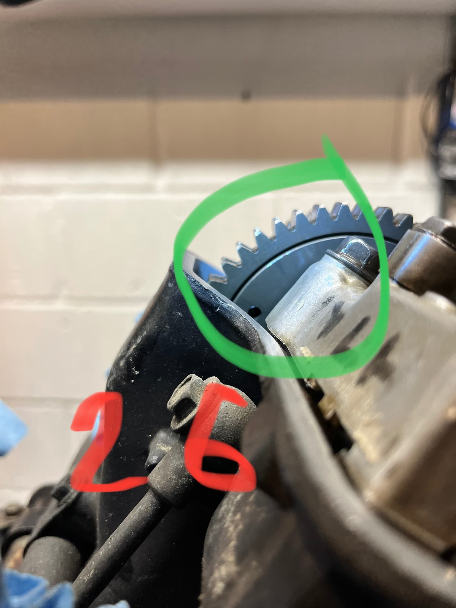
26 is LHS rear cylinder
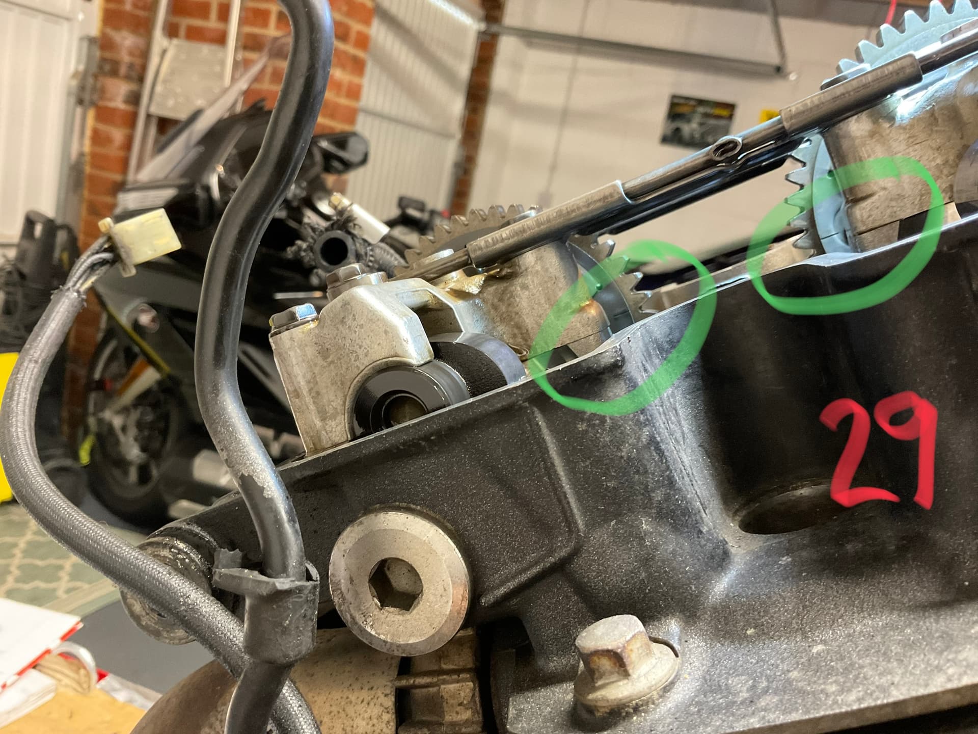
29 is RHS rear cylinder
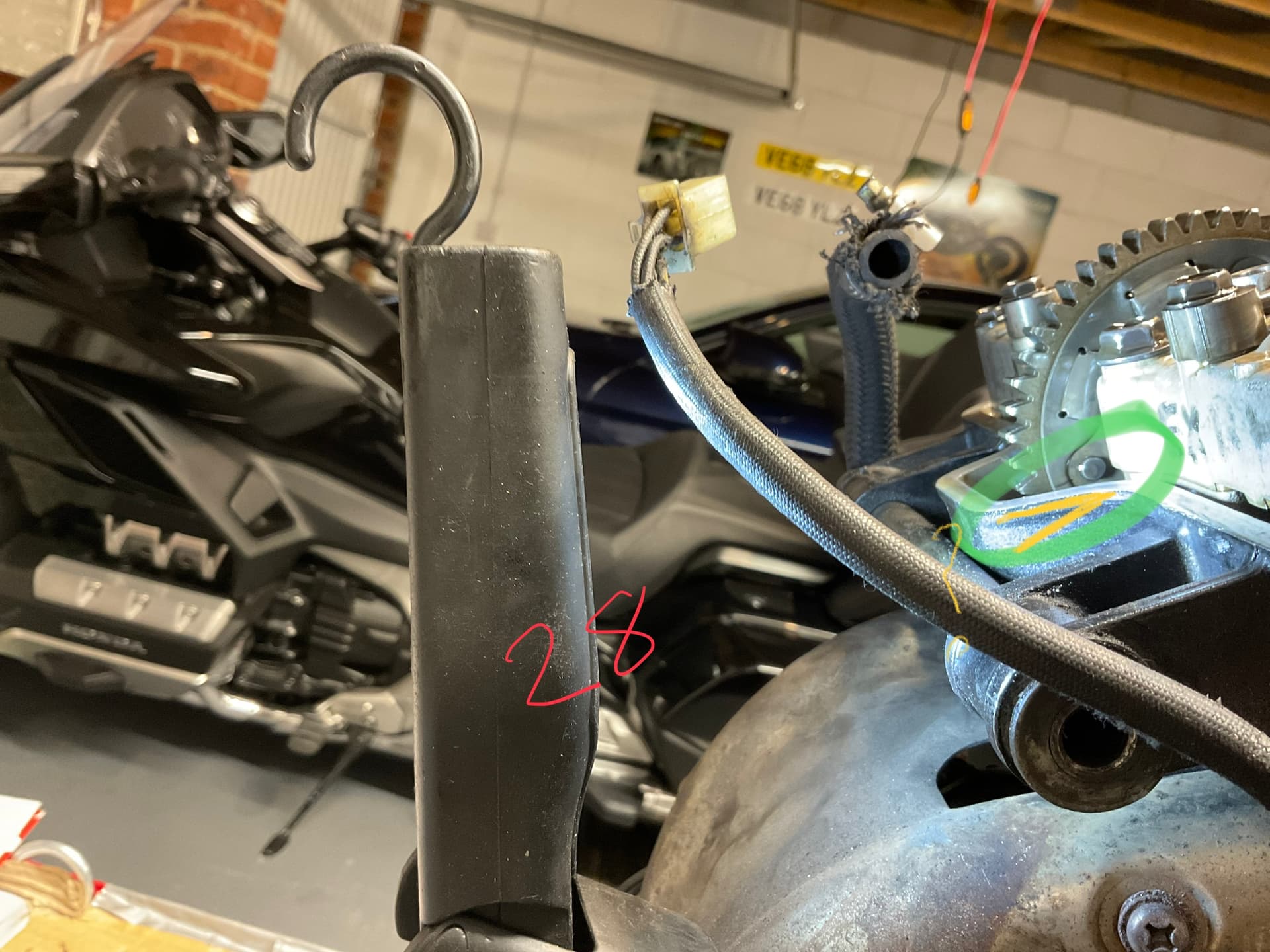
28 is RHS rear cylinder EX, RHS IN index is the same!
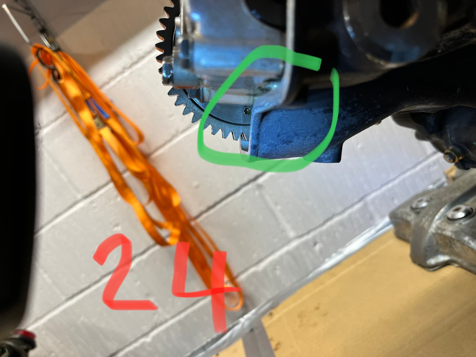
From the left of the engine all index holes should face forward and be level with the head,tdc1-3
From the right of the engine, on the rear head the two inner lines should be level with the head the two outer lines will be below the head.As per pic29
On the front head the two outer lines will be flush with the head and the inner lines will be above the head
Where are the index lines on the front cylinders?
Hi Bif, for some reason I didn’t take a picture of the front cylinder RHS, I removed the cams a while ago and sent them off to Phil joy for work.
I was writing up my notes & photos today in preparation for rebuilding and noticed this discrepancy.
I still do not have the cams back from Mr Joy yet & without the cams I can’t see what they would look like upside down so not sure if I have TDC on the wrong stroke or if the rear cam gear was a bit out…
I have also taken another look at the photos from the LHS on the front cylinder; there isn’t a hole on the IN cam gear…there is on the EX cam gear, photo below.
I am a bit stuck now and need some help?
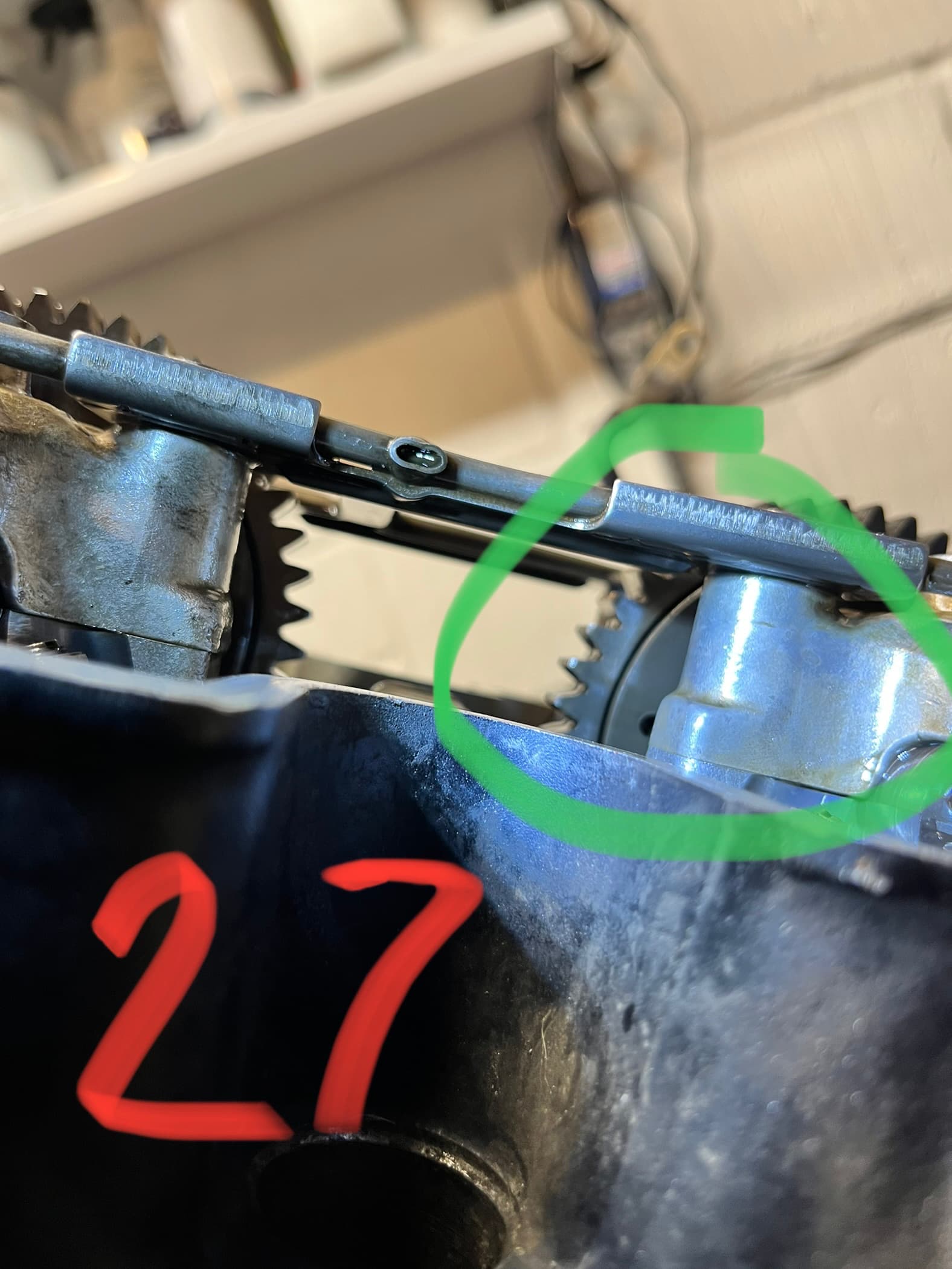
The rear head LHS had a hole in both IN and EX although EX isn’t quite in line, see photos
Hi Bif,
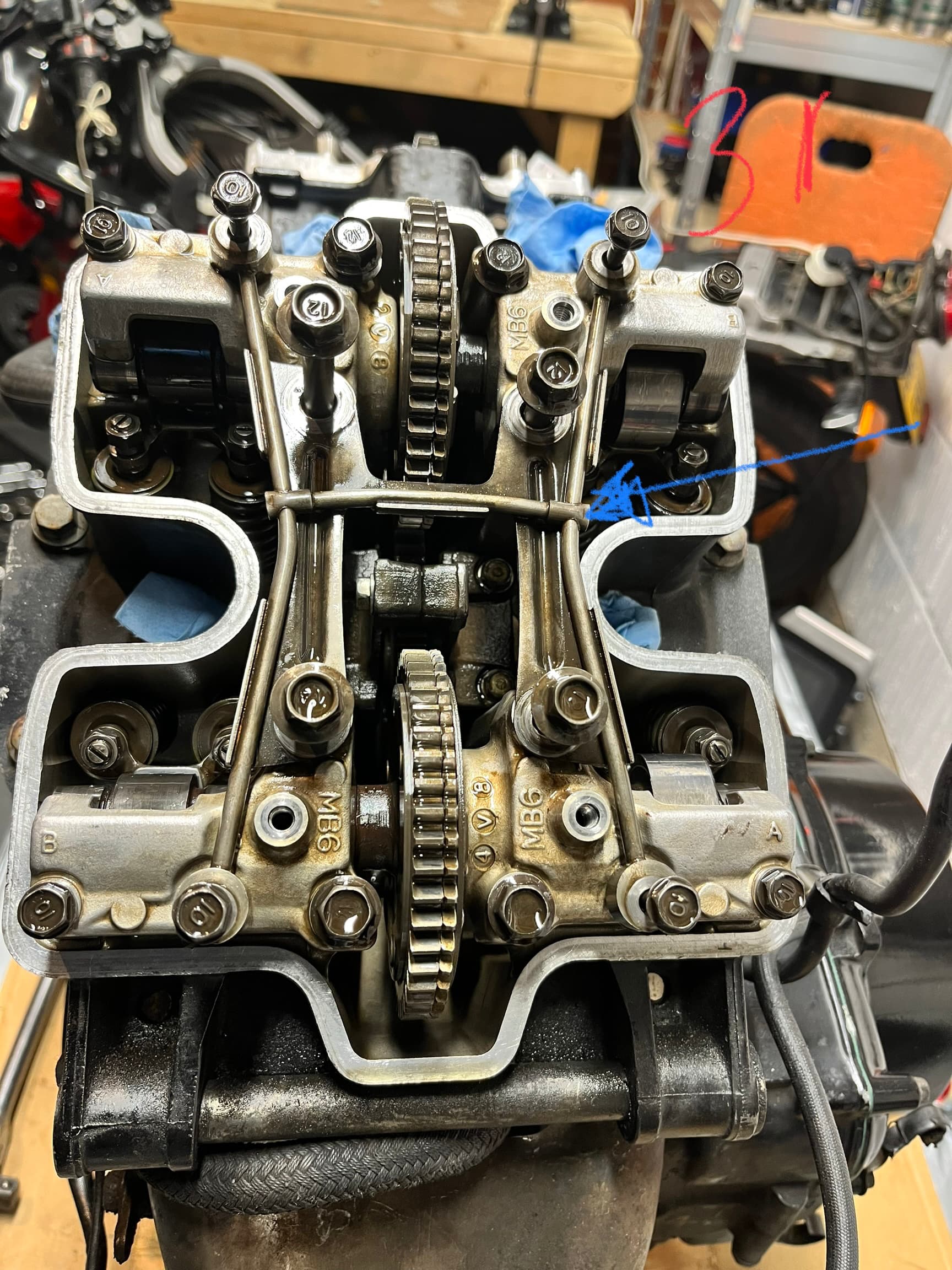
I also have a picture of the rear cylinder head from above with the cams still in situ, whilst set on TDC 1-3 (as used for this strip down) I was trying to see if I could work out if I was on TDC on the correct stroke by looking at the cams on cylinder 1 but as I do not know which way the cams rotate (clockwise or anti clockwise) I couldn’t work it out…
I am assuming the crank rotates twice to one rotation of the cams…that is correct isn’t it?
Can you tell from this photo? Does this help solve my dilemma?
the crank turns twice for one revolution of the cams and the cams rotate anti-clockwise.
The holes are only a guide on the cams,the index marks are what you need to get right.
I wouldn’t worry too much,it will be easier to sort once you have the cams back.
Thanks for the info.
When I get the cams back can I just set it up as per your info above i.e. crank on T1-3 and then set cams as per pictures OR do I have to work out what stroke the engine was on when I disassembled it before I start?
I.e. does the crank do anything every two turns to send a spark so if it was disassembled on the wrong stroke i.e. the exhaust stroke and I assemble the cams thinking it was the compression stroke it wont run? Does that question make sense?
Maybe more simply the question is: does the crank have to be at T1-3 on a particular stroke to set up the cams as per the drawing OR just be at T1-3?
Remember that it’s the cams that determine which stroke you are on,set the crank to T1-3 and fit the cams as per the pictures and you’ll be fine
That is useful to know, I wasn’t sure whether the alternator end of the crank did anything clever like triggering a spark every other stroke. But if it is all triggered by the cams then the refit should be fairly straightforward with the diagrams you gave me previously.
Thanks Bif appreciate the help.
Fry
Check your manual,the ignition pickups are on the clutch side of the engine and are triggered by a projection on the starter clutch.
It triggers on each revolution of the crank so it produces a wasted spark on the exhaust stroke.
1 Like
Thanks Bif, that was very helpful & with that information (i.e. sparks every revolution but on the exhaust stroke the spark is wasted) I now know what I am doing and think I can re assemble with some confidence.
Lets hope Phil Joy completes the cams and followers soon!!!
That’s the “official” name: Wasted spark system - Wikipedia
It wastes a spark, but saves you a coil ![]()
1 Like
Hi Bif, the cams are back (nice job) and I have been fitting them today.
In terms of aligning the marks as we said with T1-3.
The front head I can get as per the diagram so ok this question is only about the rear head.
I cannot get the rear head to match the rear diagram.
I have aligned the holes on the LHS towards the front of the bike (roughly) and the cam alignment marks on the RHS are in the same configuration as the fronts…if I align the outer lines as per the diagrams the inner lines point slightly down not up?
I have currently set it as per the photos below (which was how it was when I took it apart)
The only way to get the RHS index marks to be the same as the diagram is to turn the cams 180 degrees which would then have the holes on the LHS facing the rear of the bike…
By the way I have Revision 1 (R1) Inlet cams and Revision 2 (R2) Exhaust cams, not sure that will make any difference?
What do you think?
set it as per pic 29,the revisions could be as simple as change of supplier
Pics 28, 29 & 30 are all at the same setting, just looked a bit off as the inner lines aligned but out lines pointed slightly down
I thought about aligning the outer lines but then the inner ones were pointed slightly down
The outer and inner lines are not on the same plane,stick with the inner lines as per the diagram
Thanks for your help Bif, I wasn’t sure as the diagrams you sent have the outer lines aligned on the rear head (& its the rear head I am stuck on) but when I took it apart it was the inner lines as per the photo above…its that rear head diagram that threw me