Teambif have an 85 genuine manual with amendments.I will drop it off to PAJ who can scan the offending pages.
Sorry I havent posted earlier just pulled ma head out of my ass
regards BIF
quote:
Originally posted by bifTeambif have an 85 genuine manual with amendments.I will drop it off to PAJ who can scan the offending pages.
Sorry I havent posted earlier just pulled ma head out of my ass
regards BIF
Glad ya head’s out of your ass bif[;)][;)]…is this problem “common knowledge” then?..If Svein hadn’t pointed this out to me I think I’d have stuck my head up MY ass and said fook it !![:o)].
Look sharp please as it’s stopped me in my tracks… and c’mon PAJ…pull ya finger out !!![:D][:D]. I’ll be really interested in Hondas explanation for their fook up…if there is one…
This time tomorrow it’ll be yesterday
Yes its common knowledge ma heads bin up ma ass for a while now.The cam thing is not new tho.Just remember that you are dealing with ONE engine.If you had an inline four all your settings would be done at TDC on number one the Vee 4 is no different.
just before we get an avalanche of posts telling otherwise PAJ is riding a damn fine FE that was rebuilt by us,all cams fitted on TDC 1:3.Its been to France and back via Belgium and Holland and still runs like a sweetie.
regards BIF
PAJ has the manual and is scanning the two revised pages
BIF
Here are the scans of the January 1986 revised pages 9-16 and 9-17 of the Honda Service Manual for the VF1000R
Note the changes are highlighted “NEW” on the left hand side of the page.
[:)]
quote:
Originally posted by PAJHere are the scans of the January 1986 revised pages 9-16 and 9-17 of the Honda Service Manual for the VF1000R
Note the changes are highlighted “NEW” on the left hand side of the page.
[:)]
Brilliant bif and PAJ…thanks …just wanted confirmation of all the camshafts fitted on the T1:3…Thanks also to Svein.
Any chance/ is it possible you can make this subject a “Sticky”…for future reference to anybody who just intends to follow the manuals…and fooks up? It certainly wasn’t common knowledge to me and it’s only vf1000.com that’s enlightened me here. Again thanks.[:)]
This time tomorrow it’ll be yesterday
BIF and PAJ, these scans comfirms what I wrote
earlier in this theme.
VF1000R 1986 is different here than the VF1000F -84.
The engine, like som other 86 models like USA Magna or newer,
is line bored and with changed cams.
( Ref: Picture in your scan of VF1000R -86 BIF / PAJ )
I have not personally worked with the latest models
with line boring, just the shaft and
chain driven engines without line boring 82-85.
I do have the manuals of the different versions,
but not pictures who compares cams from early and late
models. I will get some pics one day…
I have not seen an engine number yet written from you TinyTim,
but good luck and take care. [:)]
Regards Svein T., Skien, Norway.
V45 Sabre -83, V65 Sabre -84
www.honda-v4.com
quote:
Originally posted by SveinTBIF and PAJ, these scans comfirms what I wrote
earlier in this theme.
VF1000R 1986 is different here than the VF1000F -84.
The engine, like som other 86 models like USA Magna or newer,
is line bored and with changed cams.
( Ref: Picture in your scan of VF1000R -86 BIF / PAJ )
I have not personally worked with the latest models
with line boring, just the shaft and
chain driven engines without line boring 82-85.
I do have the manuals of the different versions,
but not pictures who compares cams from early and late
models. I will get some pics one day…
I have not seen an engine number yet written from you </font id=“red”>TinyTim,
but good luck and take care. [:)]Regards Svein T., Skien, Norway.
V45 Sabre -83, V65 Sabre -84
I’m sorry…missed that request …I’ll get it posted in a day or two.
Thanks again Svein…[:D][:)]
This time tomorrow it’ll be yesterday
The best solution must be to make a list over the changes by engine
numbers and part numbers for these parts from the fiche,
some front cams must be installed at T 2-4, like the 84 1000Fe engine.
Disassembled both heads from a VF1000Fe -84 engine yesterday eng.no
SC15E-2004970
Front cams disassembled at T 2-4, Rear at T 1-3, like the other oldest V4 engines.
The most easy way in the beginning must be this -
Be sure that you have the correct workshop manual on your table,
And the original engine in the frame…
Then do some notes and take som photos before you
strip down the parts in the engine.
Some Honda V4 models got line boring in 1985, some in 1986.
I knew that F-II models was changed, but was not sure
about all of them. Looks like all 1000 Ff & F2f models was changed, yes.
Regards Svein T., Skien, Norway.
V45 Sabre -83, V65 Sabre -84
www.honda-v4.com
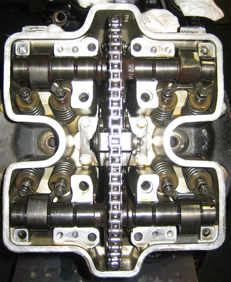
Here’s a pic of the front cylinders of the VF1000Fe 1984 engine here,
taken here yesterday,where the flywheel is rotated 90 deg
counterclockwise from T 1-3 to T 2-4.
When all the valve adjustment nuts are loosened and the screws are turned backwards,
all the rocker arms will be free from the cam lobes.
I have seen your workshop pictures of your bike earlier on the forum galleri here,
looks like the first model ?
(It’s just one more explaination pictures that can be used
together with my other pictures links earlier in this thread )
Regards Svein T., Skien, Norway.
V45 Sabre -83, V65 Sabre -84
www.honda-v4.com
Far be it from me to dispute the details you have posted Svein,it seems to me that perhaps the simple method of all cams in on the T1-3 mark which works for all the models I have worked on 84thro86 may be the way forward for those of us less adept than yourself.
regards BIF
Bif,
I’m far from beeing an expert,
but the explainations are based on Honda’s own
workshop manuals, all the explanations on the
big SabMag forum www.v4hondabbs.com ,
and the V4 engine builder / oilmod developer Dave Dodge,
here’s his words from feb 07 about this issue :
I always install the rear cams at TDC 1-3 and align the lines on the
sprockets, and the front cams at TDC 2-4 and align the dots on the sprockets.
The only exception to this is the US VF1000R with gear driven cams, which
all 4 are installed per the manual at TDC 1-3. It is possible to install
all 4 cams on the other models at TDC 1-3 with the lines on the sprockets
aligned on all 4 cams, but it is not as accurate to determine proper
position of the cams to acheive the proper firing order.
Dave Dodge - DRP
Btw, here’s a note from Honda’s own workshop manual, VF750F :
CAUTION
If you force a valve open while installing the camshaft holders,
you may damage the holders or the camshaft bearing surfaces.
It’s also some interesting articles here :
http://users.metro2000.net/~cdc/magna/mcpage.htm
under the section “Technical Sections And Issues” > “Cams”
I have modified one of my pics to
show the differences between “lines” and “dots”
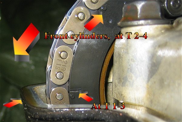
On the very first 750’s you must draw the “extra”
front cam installation dots yourself.
Regards Svein T., Skien, Norway.
V45 Sabre -83, V65 Sabre -84
www.honda-v4.com
The clymer manual is wrong.
All four cams are installed against T1-3
on the asembly line at Honda they dont have time(dont need to) to rotate the engin so only one timming mark is used .
hey guys, my name is brian, im currently living in orlando florida in the states, attending the motorcycle mechanics institute… i bought my vf1000f about 3 years ago, it has 79,501 miles on it and im currently attempting a cam chain tensioner replacement on the front cylinders, so im kind of in the same boat as you guys… im glad i found this post specially about the error in the clymer manual… i was just talking to my instructors about that same timing problem and it just didnt make sence… but anyways… i have a question… i set up my timing (which i now know to be incorrect since i was following the clymer manuals directions) and pulled the pin out of the tensioner to releave the springs tension, and it seems to have missed the chain… atleast it isnt applying proper cam chain tension right now, the only thing i can think of is that i didnt have the slipper guide in the correct notch in the cylinder, i tryd using flash lights and extendable mirrors to see down in there but i couldnt see anything usefull when i was installing it, so i just did the best “by feel” job i could, any suggestions on properly installing the slipper guide? or ways i can find out if its in the notch before i pull the pin the next time? any help would be greatly appreciated
the best part about a harley carb is that its a honda (keihin is currently owned by honda)
quote:
Originally posted by BrianAhey guys, my name is brian, im currently living in orlando florida in the states, attending the motorcycle mechanics institute… i bought my vf1000f about 3 years ago, it has 79,501 miles on it and im currently attempting a cam chain tensioner replacement on the front cylinders, so im kind of in the same boat as you guys… im glad i found this post specially about the error in the clymer manual… i was just talking to my instructors about that same timing problem and it just didnt make sence… but anyways… i have a question… i set up my timing (which i now know to be incorrect since i was following the clymer manuals directions) and pulled the pin out of the tensioner to releave the springs tension, and it seems to have missed the chain… atleast it isnt applying proper cam chain tension right now, the only thing i can think of is that i didnt have the slipper guide in the correct notch in the cylinder, i tryd using flash lights and extendable mirrors to see down in there but i couldnt see anything usefull when i was installing it, so i just did the best “by feel” job i could, any suggestions on properly installing the slipper guide? or ways i can find out if its in the notch before i pull the pin the next time? any help would be greatly appreciated
the best part about a harley carb is that its a honda (keihin is currently owned by honda)
the best part about a harley carb is that its a honda (keihin is currently owned by honda)
err sorry about that rather pointless quote, i meant to include the update but im still trying to figure this thing out… not to computer savvy… anyways… turns out the problem wasnt the tensioner at all, simply the cam timing, thanks guys
the best part about a harley carb is that its a honda (keihin is currently owned by honda)
BTW,
Honda’s later manual for the -85 VF1000F and F-II has a better explaination for this issue than the first manual for the -84 VF1000F. 
Regards Svein T., Skien, Norway.
V45 Sabre -83, V65 Sabre -84
www.honda-v4.com
well i opened a can of worms didnt i, my bike is back together but wont go cdi unit has packed in and iam having problems getting one
Hi
Bit of a deep one this seems. I’ve just rebuilt my engine but took the precaution of photographing and noting the cam positions before disassembly. As mentioned, the manuals are an embarrassment to the so called ‘authors’. Funny as!
Sven’s explanation is, I think, what I had but my cams look nothing like his examples on the ends and the photos are a little confusing with regard to his mark-up. What Sven was trying to say is as follows and is correct:
CAM TIMING VF1000F
-
Both cam chain tensioner mechanisms must be retracted and locked with a length of wire. Ensure that the lower location foot of each tensioner blade is in its location slot in the crankcase.
-
With all tappets screwed out as far as possible and nipped on their locknuts, from the left side of the engine turn crank to T1-3 setting and set the rear cylinder bank as follows:
Note: The cam sprocket bolts do not need to be loosened to do this procedure.
a) Make sure the cam chain follows its chain guide so that there is no slack in the chain when you install the inlet cam. Any slack should be on the exhaust cam/crank side of the chain run.
b) Put the inlet cam in its bearings so that its No.3 cam lobe is just leaning towards the exhaust cam position with the lines on the left side of the cam sprocket level with the head surface.
c) Put the exhaust cam in its bearings so that its No.3 cam lobe is just leaning towards the inlet cam with the lines on the left side of the cam sprocket level with the head surface.
d) Install the cam bearing caps and bolts and tighten by hand with a socket (not wrench) to locate them in position.
e) Install the four bolts socket-tight at each cylinder bank to locate the cam chain tensioner mechanism in position.
f) Install the oil pipe and install the bolts to a socket-tight location.
g) Torque tighten the cylinder head/cam bolts to the specified torques:
9 mm = 31 – 34 Nm (1, 2, 3, 4, 5, 6, 7, 8)
8 mm = 15 – 18 Nm (9, 10, 11, 12)
6 mm = 7 -10 Nm.
h) Torque tighten the four bolts at the cam chain tensioner mechanism (7 -10 Nm).
i) Remove the locking wire/eqmt from each cam chain tensioner mechanism.
- From the left side of the engine, turn the crank anti-clockwise 90 degrees to align the T2-4 mark on the alternator rotor with the crankcase split line and set the front cylinder bank as follows:
Note: The cam sprocket bolts do not need to be loosened to do this procedure.
a) Make sure the cam chain follows its chain guide so that there is no slack in the chain when you install the exhaust cam. Any slack should be on the inlet cam/crank side of the chain run.
b) Put the exhaust cam in its bearings so that its No.4 cam lobe is pointing directly towards the inlet cam position with the solitary dots on the left side of the cam sprocket level with the head surface.
c) Put the inlet cam in its bearings so that its No.4 cam lobe is pointing directly towards the exhaust cam with the solitary dots on the left side of the cam sprocket level with the head surface.
d) Install the cam bearing caps and bolts and tighten by hand with a socket (not wrench) to locate them in position.
e) Install the four bolts socket-tight at each cylinder bank to locate the cam chain tensioner mechanism in position.
f) Install the oil pipe and install the bolts to a socket-tight location.
g) Torque tighten the cylinder head/cam bolts to the specified torques.
h) Torque tighten the four bolts at the cam chain tensioner mechanism (7 -10 Nm).
i) Remove the locking wire/eqmt from each cam chain tensioner mechanism.
- Set the tappets as follows;
a) With the plugs removed, turn the crank until a cam lobe tip is 180 degs from its valve actuator. Set the two tappet clearances to 0.005 in (0,012 mm).
b) Do this for each cam lobe.
Best Regards
Trevor
ITS GOING woophe!