can some one HELP ive just finished biulding my engine but iam begining to doubt weather ive got the cam position right ive got a honda manual but its seems so ambiguous. can someone tell me how, ive set timeing mark at 1.4 and put cams in as book states all timing marks pointing at inlets and exhaust. but still i dont belive its right [?][?] thanks.
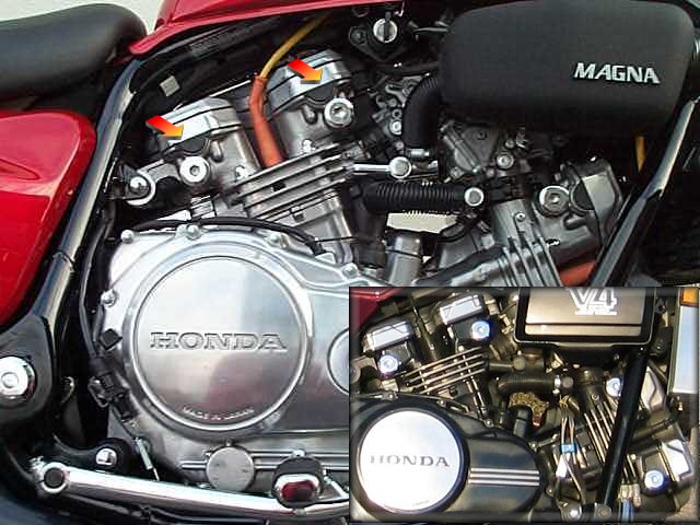
When correctly set, the cam index marks align with the rocker-cover gasket faces. It’s not very well shown in the manual, but it’s easy to see…
Tip: - If you’re not 100% certain of the cam timing, leave the tappets nice and loose while you check it as follows…
Turn the Generator rotor to “T1:4” (No 1 Cyl should be on compression) - the timing marks on the two front cams should be in line with the front gasket face - one tooth out will have them out of line - check both sides of each cam as the difference is easier to see this way…
Turn the Generator rotor to “T2:3” (No 3 Cyl should be on compression) - the timing marks on the two rear cams should be in line with the rear gasket face - check as above…
When you’re happy that the timing is OK, rotate the engine SLOWLY, for four complete revolutions… Stop every 1/4 turn and check the camchain tension at that point… If you’re happy that both chains are tensioned properly, re-check the cam timing (as above) and set the valve clearances…
Should be nice and quiet now… A compression check on my VF1000 (after setting as above) showed about 205 psi on each cylinder (just for info)…
Have Fun
Jeff
MITI-BABE
Sunny Scotland - North(ish)
VF1000FE - (MB6 - '84)
XS1100S - (5K7 - '85)
thanks for that but ive got no cam chains its gears , and my timing marks are T1;3 and T2;4. so iam still in the dark
Stephen
Apologies for that…
Procedure corrected as follows:
When correctly set, the cam index marks align with the rocker-cover gasket faces. It’s not very well shown in the manual, but it’s easy to see…
Tip: - If you’re not 100% certain of the cam timing, leave the tappets nice and loose while you check it as follows…
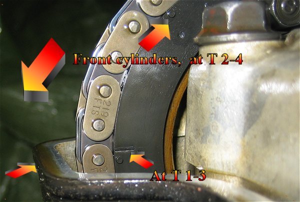
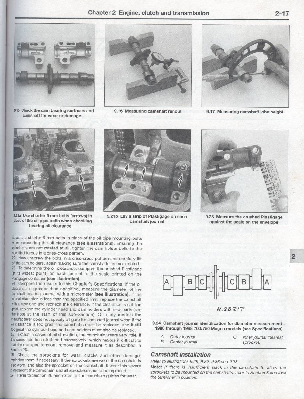
Turn the Generator rotor to “T1:3” (No 1 Cyl - rear left) should be on compression) - the timing marks on the two rear cams should be in line with the rocker cover gasket face - one tooth out will have them out of line - check both sides of each cam as the difference is easier to see this way…
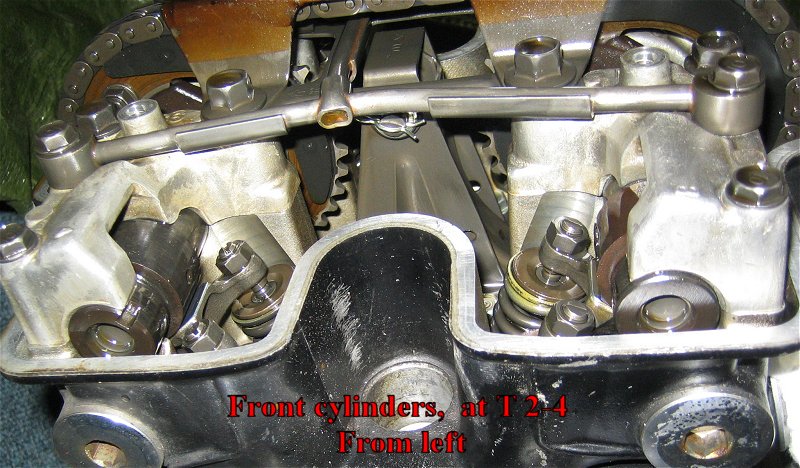
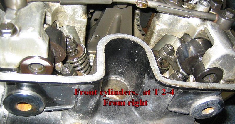
Turn the Generator rotor to “T2:” (No 4 Cyl - front right should be on compression) - the timing marks on the two front cams should be in line with the rocker cover gasket face - check as above…
When done, you should VERY SLOWLY rotate the engine through two complete revolutions with the spark plugs out. STOP if you feel any resistance and go back and check the marks… Check the marks each time the T1:3 and T2:4 marks line up…
Sorry about the mix up…
Jeff
MITI-BABE
Sunny Scotland - North(ish)
VF1000FE - (MB6 - '84)
XS1100S - (5K7 - '85)
sorry ive not said thanks yet for your reply but thanks. i take it you turn it anticlockwise,90 degrees. ive done that but when i turned the engine over its hitting a vavle. ive bought a manual from states but thats a waste of space. jeff can i contact you if atall posible thanks
quote:
Originally posted by stephensorry ive not said thanks yet for your reply but thanks. i take it you turn it anticlockwise,90 degrees. ive done that but when i turned the engine over its hitting a vavle. ive bought a manual from states but thats a waste of space. jeff can i contact you if atall posible thanks
Sephen…where are you?..if you want , I can photocopy the Workshop Manual and send it to you…
my e-mail addy is
[:D]
This time tomorrow it’ll be yesterday
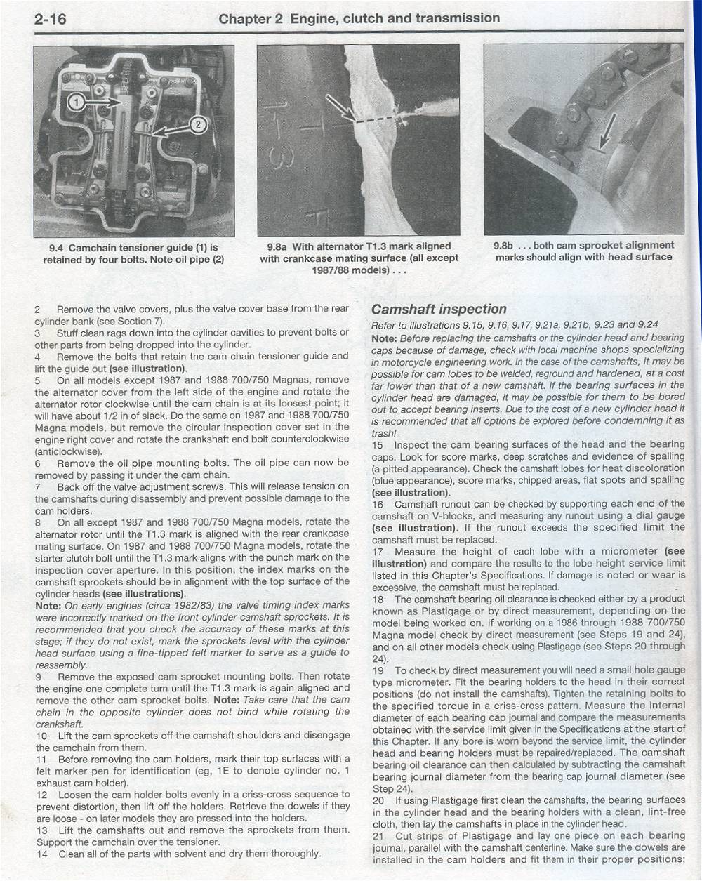
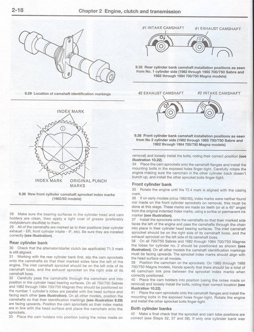
The right way of doing the cam timing is,line timing mark 1:3 up with crankcase joint and put all cams in front and rear cylinders with dots faceing forward and lines level with cam bearing split line.
quote:
Originally posted by stephenThe right way of doing the cam timing is,line timing mark 1:3 up with crankcase joint and put all cams in front and rear cylinders with dots faceing forward and lines level with cam bearing split line.
No no no…Crank position T1:3 is for the two camshafts in the rear cylinder alignment only. The T2:4 position is for the front cylinder camshaft alignment. WELL…THIS IS ACCORDING TO THE CLYMER MANUAL…AND LOOKS NOW< TO BE INCORRECT…SEE MY NEXT POST !!!
This time tomorrow it’ll be yesterday
a friend has been in touch with honda uk thay insist this is right for a vf1000r with gear driven cams if you put front cams in on 2;4 you risk bending ex/valves. ive put my front cams in on 2;4 and valves hit piston. put them all in on 1;3 nothing hits
quote:
Originally posted by stephena friend has been in touch with honda uk thay insist this is right for a vf1000r with gear driven cams if you put front cams in on 2;4 you risk bending ex/valves. ive put my front cams in on 2;4 and valves hit piston. put them all in on 1;3 nothing hits
[:0][:0]…so sorry Stephen…how have I missed your post about not having cam chains , but being gear driven[:o)]. Thank fook you didn’t take any notice of me[:D]… Very sorry mate…I was so confident about the subject as I have just rebuilt my engine from the barrels up and can now put the valve gear in almost ( almost ah seh!)…blindfold and without any help…mind you I have had about four attempts at it…I end up leaving it half done…then get waylaid for weeks, then go back and think “fook it, I’ll start again”…but as they say, whoever they are, practice makes perfect.
And if you’rw out there PAJ, I fully understand the Honda Cam tool and its raison d’etre…ingenious !!! I will be using it this week, once the snow has gone and the temperature in my garage has gone up a bit !! Thanks in anticipation of having perfectly timed valves and perfect clearances[:D][:D][:D][:D]
This time tomorrow it’ll be yesterday
Shock…horror…All is not what it seems…and I haven’t been drinking honestly.
This subject of cam position/timing has really got hold of me…and I really need help now.
Further to my last post about doing this job that many times that I had become quite adept at it…please disregard. [:o)][:I]
Last night …all I had left to do was set the valve clearances… all went fine until I set the left exhaust valve on the front cylinder. Once set I couldn’t turn the engine over without the front left exhaust valve being in the open position with the front piston at TDC at the same time…i.e piston hitting valve…[:(!]
I had meticulously followed the instructions for fitting the Cam shafts for front and rear cylinders from the Clymer manual which seemed to me to be a lot more specific and detailed in the step by step instructions than the Honda Workshop manual.
I have been over the procedure several times …correct camshafts, correct way round etc etc…and the only thing I can find that is different between manuals is this.
In the Clymer manual the rear cylinder camshafts are fitted with the crankshaft in the T 1:3 position. Once these two are fitted, the Clymer manual then says to rotate the crankshaft 90 degrees anticlockwise until timing mark T 2:4 is made. The front camshafts are then fitted with the crankshaft at the T 2:4 mark. This is how I have done it. However I did notice that at this crankshaft position, the front cylinder exhaust camshaft when fitted in its correct position, is putting one of the pair of exhaust valves under compression, even with the valve adjusters backed right off.
Reading the Honda Workshop manual however…there is only reference to the T 1:3 mark on the crankshaft being used for the fitting of all four camshafts…
As I sit here and write and contemplate, I am of the opinion , at the moment, that the Clymer Manual is totally fookin wrong.[}:)]
Anybody out there help please? This really should be a straightforward “piece of piss”
[:)]
This time tomorrow it’ll be yesterday
Hello, I can help you with this,
I will also take some photos of a VF1000F engine here on the floor in my workshop,
- explainations for the chain driven and the shaft driven models.
I will post a new message within some hours.
Regards Svein T., Skien, Norway.
V45 Sabre -83, V65 Sabre -84
www.honda-v4.com
1 Like
quote:
Originally posted by SveinTHello, I can help you with this,
I will also take some photos of a VF1000F engine here on the floor in my workshop,
- explainations for the chain driven and the shaft driven models.
I will post a new message within some hours.Regards Svein T., Skien, Norway.
V45 Sabre -83, V65 Sabre -84
Thanks Svein…will desperately look forward to it…[8D]
If you have trouble posting photos ( I have not mastered it yet)…can you send them to me at …
Thanks.
This time tomorrow it’ll be yesterday
Hello, here’s som pics and parts of manuals for the chain & shaft
driven classic V4’s.
I will try to explain as good as poosible,
my english writing is not excellent but ok to understand I hope.
I do have a VF1000F engine here for repair
but I have not started the work yet.
The engine needs new cams, rockers, tensioners,
and at the same time I will plane the heads and fit new
head gaskets. + an oilmod. So I have taken some pictures.
Click the links and you will find the camshaft install info from the
VF1000F & F-II manual, VF750F manual and VF750 & 1100 manual (shaft)
- my pictures from today with text.
About the workshop manuals :
Yep, the first editions had errors, books from Honda,
Clymer but also Haynes.
It’s different versions of these workshop manuals …
It’s always smart to record all small differences
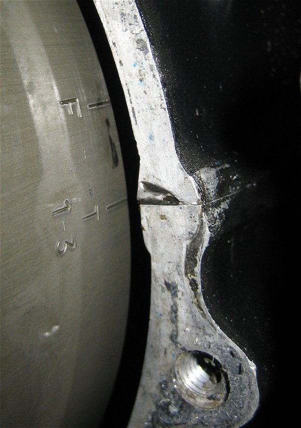
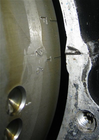
before stripping down the engine, because all 8 of the punced marks
on the sprockets are not often 100% aligned with the head egde.
Sometimes it looks like the sprocket are 1/2 teeth wrong one way or another.
so it’s easy to use some extra time on this…
It’s also very important to not mix up the parts - of course…
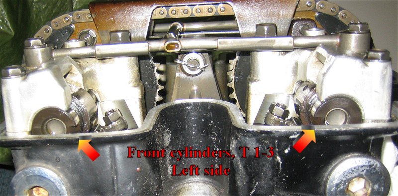
Left rear - No 1 cyl
Left front - No 2 cyl
Right rear - No 3 cyl
Right front - No 4 cyl
Firing ordrer :
1-2-3-4 Shaft / 1-4-3-2 Chain
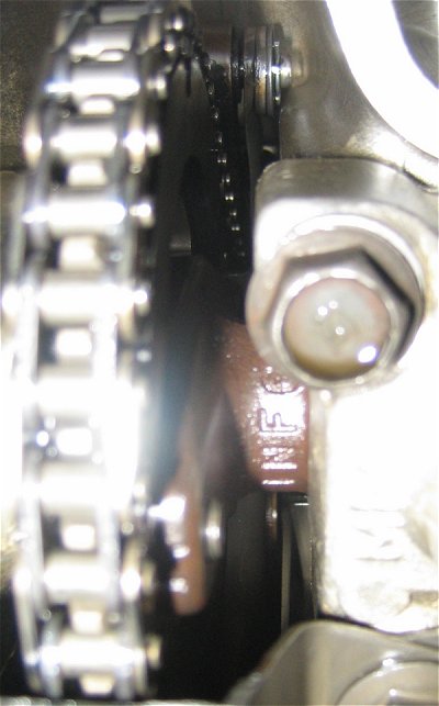
Cam ID :
ER = Exhaust rear.
IR = Intake rear.
IF = Intake front.
EF = Exhaust front.
You will find the ID on the camshaft
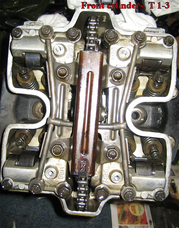
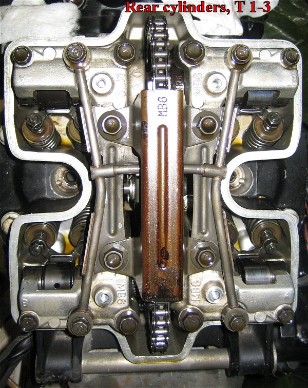
where the sprocket are placed.
All of these ID’s should face UP at the same time
at T 1-3 !!!
If you cant see the marks, turn the engine one full turn.
On the other side of the cam theres often another
mark like “R2” “R3” means release numbers…
The cams on the pictures are R2, I don’t know
if the other releases has the same details/notches
like R2 for VF1000F.
Install the cam closest to the camchain guide mounted
in the engine first, not the guide fitted on the tensioner -side
(which side depends on shaft or chain drive model)
The difference between the 750 models are
just that everything is opposite from shaft to chain,
because of the opposite engine rotation.
( Btw: In the Haynes book for VF750/1100 Shaft drive models,
there’s also an mistake,
because after the installation of the rear cams
the engine must be turned clockwise (shaft drive)
from T 1-3 (directly) to T 2-4. But the engine must be turned
to T 2-4, then to T 1-3 and at last to T 2-4 again
to get the front camshaft installation correct. )
The front cam installation at T 2-4 is described in the
small pdf manuals here, in details, but …
It’s also some small marks/warts at the sprocket 6 teeths from
the T 1-3 line mark on the VF1000F engine cam sprocket, to help you.
These extra marks must be aligned with the
head edge at T 2-4 front.
At this point the camshaft lobes should point
straight away from each other on front cyl 2 (left)
and straight against each other at front cyl 4 (right)
It’s also a good idea to use a little locktite on the
sprocket screws…
Double & triple check everyting after the installation
at the T 1-3 mark.
I’ll hope this will help you. [:D]
Right click on link,
and select “Save as” to save the file on your computer.
-------------- Chain drive ------------
http://www.honda-v4.com/sabmag/download/vf1000f-camtiming.pdf
http://www.honda-v4.com/sabmag/download/vf750f-camtiming.pdf
T 1-3 pictures VF1000F
T 2-4 pictures VF1000F
------ Shaft drive ----------
Regards Svein T., Skien, Norway.
V45 Sabre -83, V65 Sabre -84
www.honda-v4.com
Thanks for all that hard work Svein…the photographs are a great help.I’m still unclear as to what position I fit the front pair of camshafts…
What I can’t believe is that some of the manuals are wrong! Is that right?..I just find it hard to believe.
In a nutshell for me…my problem is once I have fitted the rear camshafts on the crankshaft mark T 1:3…what do I do NEXT to fit the front pair of camshafts… The manual says to move the crankshaft 90 degrees anticlockwise to the T 2:4 mark and THEN fit both front camshafts…but when I do that the front exhaust camshaft is opening the No2 cylinder exhaust valves !!..at Top Dead Centre for the front pistons !!!.
Contrary to these instructions, the final test according to the manual is to rotate the crankshaft again to the T1:3 position . At this position it says ALL four camshaft marks should line up with the top face of the cylinder heads. Surely impossible if the front pair of camshafts have been fitted 90 degrees “earlier” than the rear camshafts.
confused.com You bet !!!
C’mon someone cas tsome brighter light on this…
This time tomorrow it’ll be yesterday
Further development today re the above anomalies. Tried unsuccessfully to contact Honda UK…they are useless.[}:)] Then I remembered a small one man Motorcycle Repair shop about 10 miles away. He’s only a small business, but knows his stuff and been around for years. I also remembered someone saying he once worked as a Honda mechanic for a Honda race team way way back…many moons ago.
So I gave him a ring on the off chance he may be able to direct me to someone who may know. I started to explain my predicament with the front cams being in the wrong place if I followed the instruction manual and set them on the T 2:4 crankshaft position and before I could explain further he said he remembered that the Honda Factory Instructions were initially wrong and admitted to be wrong. He further stated that Honda, when they realised the mistake, published an amendment to the manual. He also says that unfortunately the amendments tended to get lost/misplaced and also the Clymer manual was wrong on some editions because they copied from the incorrect Honda Instructions in the first place !!!
The bloke seemed to be very “up” on the subject and has asked me to call back tomorrow when hopefully he will have found the amendment to the manual concerning the camshaft positions. He also mumbled something about the front camshafts being redesigned lobe position to shaft wise to allow timing of all 4 camshafts off the one T 1:3 crankshaft position…
I will keep you informed of any news !!
This time tomorrow it’ll be yesterday
Hello, read this once more,
It’s also some small marks/warts on the sprocket 6 teeths from
the T 1-3 line mark on the VF1000F engine cam sprocket, to help you.
These extra marks must be aligned with the
head edge at T 2-4 front.
At this point the camshaft lobes should point
straight away from each other on front cyl 2 (left)
and straight against each other at front cyl 4 (right)</font id=“blue”>
And I have taken pics for you too !
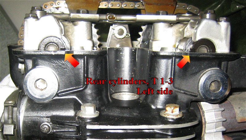
- Rear cyl must be at T 1-3 and cam marks aligned/ID UP (Like EX-R)
- Then rotate the flywheel counterclockwise to T 2-4 90 deg,
- Install the cams as described with the marks & 6 teeth
as described, the same way and angle/ position as the rear
cams then - of course ! (Yes, the cams - not the cam lobes)
You have the pictures .
Can’t be that difficult heh ?
If you move the rear cams forward 6 teeths, you must install
the front cams 6 teeth forward, it’s only because in that position
the cams lobes in front are free from the rockers, that’s why.
It’s logical if you want to place all the marks in the same position at T 1-3 , isn’t it ? Check my pictures.
4. Check all marks by turning the engine around 2 x 360 deg. after tighten the bolts by hand force only. Got it? [;)]
The pdf manual here for 1000 isn’t the first,
because the F-II model is described too.
My engine pics are from an 1984 engine,
the model with 16" front wheel - made in 84 only for
the Euro market, 84 Usa, and 84 AND 85 for Canada.
I have not heard that the cams was changed that way on 1000F’s
but on later Usa/Can 700/750 Magna’s & SuperMagna.
But if there’s a change, it must been done on some few
and the latest models with line boring, viewed here :
I’m still learning [:D]
(It’s always possible to do an mistake for everyone of us)
Yes, the first books had all mistakes around this.
And it’s very frustrating, because books like this must be correct…
[xx(]
Regards Svein T., Skien, Norway.
V45 Sabre -83, V65 Sabre -84
www.honda-v4.com
quote:
Originally posted by SveinTHello, read this once more,
It’s also some small marks/warts on the sprocket 6 teeths from
the T 1-3 line mark on the VF1000F engine cam sprocket, to help you.These extra marks must be aligned with the
head edge at T 2-4 front.
At this point the camshaft lobes should point
straight away from each other on front cyl 2 (left)
and straight against each other at front cyl 4 (right)</font id=“blue”>And I have taken pics for you too !
- Rear cyl must be at T 1-3 and cam marks UP
- Then rotate the flywheel counterclockwise to T 2-4 90 deg,
- Install the cams as described with the marks & 6 teeth
as described, the same way and angle/ position as the rear
cams then - of course ! (Yes, the cams - not the cam lobes)
You have the pictures .
Can’t be that difficult heh ?
If you move the rear cams forward 6 teeths, you must install
the front cams 6 teeth forward, it’s only because in that position
the cams lobes in front are free from the rockers, that’s why.It’s logical if you want to place all the marks in the same position at T 1-3 , isn’t it ? Check my pictures.
4. Check all marks by turning the engine around 2 x 360 deg. after tighten the bolts by hand force only. Got it? [;)]The pdf manual here for 1000 isn’t the first,
because the F-II model is described too.
My engine pics are from an 1984 engine,
the model with 16" front wheel - made in 84 only for
the Euro market, 84 Usa, and 84 AND 85 for Canada.
I have not heard that the cams was changed that way on 1000F’s
but on later Usa/Can 700/750 Magna’s & SuperMagna.
But if there’s a change, it must been done on some few
and the latest models with line boring, viewed here :
I’m still learning [:D]
(It’s always possible to do an mistake for everyone of us)Yes, the first books had all mistakes around this.
And it’s very frustrating, because books like this must be correct…
[xx(]Regards Svein T., Skien, Norway.
V45 Sabre -83, V65 Sabre -84
Thanks Svein…I need to have a good read of this to digest it…I need to have a few days away from this problem at the moment as I am getting very frustrated and need to calm down. I will let you know how I get on . By the way…you said you have posted pics…I can’t see any, just two pics of a table of frame numbers??
Thanks again .
Tim
This time tomorrow it’ll be yesterday
Hello, I have posted a lot of pics earlier in this tread,
where you can see how the cams & lobes are placed on
the VF1000F engine here at T 1-3 and T 2-4.
Have a nice weekend. [8D]
Regards Svein T., Skien, Norway.
V45 Sabre -83, V65 Sabre -84
www.honda-v4.com
quote:
Originally posted by SveinTHello, I have posted a lot of pics earlier in this tread,
where you can see how the cams & lobes are placed on
the VF1000F engine here at T 1-3 and T 2-4.Have a nice weekend. [8D]
Regards Svein T., Skien, Norway.
V45 Sabre -83, V65 Sabre -84
Thanks Svein…ys I’ve got the pics from your other post…I’ll go back over them with the extra imformation about the “6 teeth” on the camshaft sprocket…I have looked at the sprockets and yes I see the little marks that are 6 teeth away from the “horizontal” marks…I just find it hard to believe that this is the first mention I have ever heard of this from you.
What on earth were Honda playing at !!!
This time tomorrow it’ll be yesterday