Would any of the learned collective know what current the cooling fans draw?
I’m finally getting round to fitting a manual on/off switch to my FF, but have a level of concern that the suitably discreet switches that I’ve found won’t be up to the job.
Any surge loading has to be less than 10 amps at 12v so if my understanding of ohms law is correct any switch rated for 240v and 1 amp will handle twice the load of the fans,I’m sure Gaz will keep us right on this
I’ve just asked my old man (he designed switch gear and transformers used in power stations, and latterly the stuff inside Nimrods).
He tells me that any surge current will be huge for a couple of microseconds as the motors start to rotate, but will drop down to nominal exponentially within those same microseconds. The upshot is that operational current draw must be less than 10a, otherwise the fuse would blow. The peak current at start up isn’t flowing for anywhere near long enough to be an issue.
The switch I’ve bought is 12v, 20a continuous rated, so all is good.
Your both correct, as long as it can handle 10 amps continuously it will be fine. I bought a really nice handle bar mounted switch that lights up when on but had to fit a relay into the circuit as the original fan switch switches the neutral so the light wouldn’t work. The lengths we go to to make something look good!
Took a Fan off the shelf and measured the running current @ 14.0Vdc (actual running voltage).
It draws 2.5 amps, so 2 fans draw 5 amps.
The short Start-Up current would be more, so a 10A fuse is appropriate.
Those little fans move a decent amount of air!
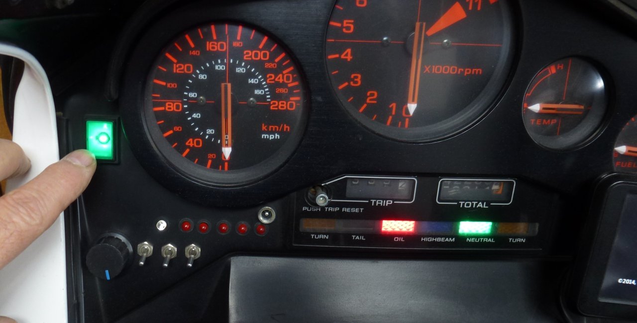
I first had a regular Toggle Sw on the dash, but kept forgetting the fans were ON.
So I replaced it with a Push-On Push-Off Illuminated Sw.
Easy to notice so I don’t forget AND Push-On/Push-Off is much easier to operate when riding than a Toggle, just touch it.
The round jack is for power for an old riding jacket (good for 4A).
The switches and LEDs were for a Radar Detector I had install’d, back in the '80s.
It got wet, fail’d, I removed it, but removing the LEDs & Switches would leave holes, so I left’em in.
I might program up a Arduino Nano to make them blink in random mode (look like a Security Alarm?).
The knob runs a 15A PWM controller for my new heated suit (hand sewn 28awg mutlistrand in the jacket, pants and heat pads in the boots). Suited up I’ll take over 10A (for those days at or below freezing).
I should really install a VoltMeter/Ammeter,… see when I’m asking for too much.
GPS just visible on right.
Air Temp Gauge not visible.
Hi Chris,
Your 12V/20Amp DC Switch will work just fine. The important thing here is that you use a 12Volt Direct Current Switch which is rated equal to or greater than the amperage of the fuse. The higher the amperage rating of the switch (at 12 volts) means the more reliable the switch will be because the switch will be made stronger to take the extra current and the Fuse will blow at whatever it is rated at. A 240Volt AC(Alternating current) switch may or may not work for very long, because AC switches are made to work a little differently than DC switches. Direct Current is more severe on switches than Alternating Current when switched on and off. DC current causes greater arking on slower moving switches (AC) so good DC switches are made to disengage or engage more quickly than AC switches to alleviate arking across the make/break joint which will destroy the contacts prematurely. The switches have to match the Voltage, and the Current but most importantly it has to match DC or AC. Bikes are 12 Volt DC, use the correct switches for better results and less problems. Of course some AC switches have worked and will continue to work on DC circuits but they are not designed to and maybe won’t last as long. As an interesting example; In Australia when building motor homes/Caravans with 12 Volt DC electrical systems, it is illegal to use 240 volt AC Sockets and light switches. Only electrical fittings rated for 12 Volt DC are supposed to be used for safety reasons.
Again, I have tried to put it in the simplest and easiest way to understand what I was taught to do.
John
I would never have thought that there was such a difference between AC and DC switches. That just illustrates why I chose mechanical engineering over this electrickery malarkey.
No Problems Chris, I got caught out a couple of times in the past. It is also one of the reasons they use relay/solenoid switches on 12/24 Volt DC systems, because they are a fast action on and off switch. The other reason is to not put high amperages through your ignition switches etc. Also the reason they put a condenser/capacitor across the old points ignition systems to stop excessive arcing (yep I spelled it right this time) on the contacts. As I have said before it is a bit tricky sometimes but if I can help or offer advice to you or anyone else, I am quite happy to do it.
I’ve successfully installed the override swith for the fans. All is good.
I then thought afterwards that it would be a good idea to fit an LED to said override circuit to alert me to when the fans are running.
I’m led to understand that said LED would need to have a 12v supply into it, with the earth being connected into the upstream tapping for the switch (logic - the switches are in the earth return from the motors, so by connecting the earth upstream of the switch it would allow the LED to illuminate if either the thermal or manual switch is closed).
If that is correct, can you suggest an easily accessible 12v supply that is switched by the ignition switch that I can tap into? I might as well fit the LED while the fairing’s off.
Hi Chris,
Let me think about that will get back to you. As a first thought I would think the easiest way would be to replace your toggle switch with an illuminated switch but because it is switching the earth side will have to think more about it. The other thing is VF1000Fe put an illuminated switch on his bike so he will know what he did to get it to work. Fitting a relay might work with power from the ign switch or fans switching a positive to a light at the same time it switches the negative to earth. garyb fitted a relay so he should know how to do that. Let me think about it and get back to you, because you can’t switch a light on from the earth side of the circuit unless you have power on the other side. Also the little I know about electronics if you use a true LED then you will have to put the correct size resister in circuit for twelve volts supply. I might try some practicle things over the weekend to jog the memory.
John
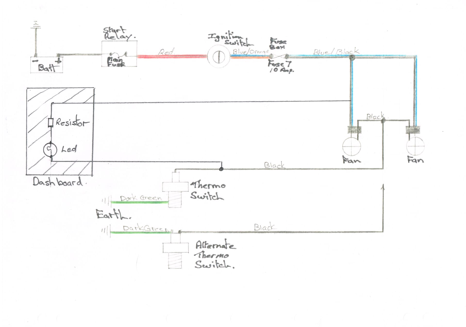
Sorry had a brain fade yesterday. I am attaching a copy of the mud map showing how to fit the led. Easier to get to the positive going to the fans and also the negative going to the Thermo switch. This should give you a light when the fans run regardless of which switch you use because the positive comes from the fans. You will need a 560 Ohm resister according to Faxe and an ordinary 12 volt Led. If your new switch is working then leave it as is. If you run a double wire down to the fans then connect as they are in the drawing then you should get a light when you should. Another way to ground the earth wire is just join it to the earth side of the switch that you have just installed. If you decide to install a normal 12 volt globe light then you don’t need the resistor in the circuit. Now I just have to remember how to attach a file.
John
No problems Chris. I am sure you could teach me a lot about mechanical engineering. If you look at the mud map, with the alternate Thermo switch at the bottom, this would also be the right wiring for an ordinary manual switch. Hopefully that is the way you wired it up.
John